Single Phase Energy Meter Phasor Diagram
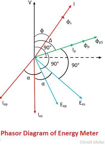
What Is Energy Meter Definition Construction Working Theory Circuit Globe

Three Phase Transformer Connections Phasor Diagrams Transformers Connection Diagram

Diagram Single Phase Phasor Diagram Full Version Hd Quality Phasor Diagram Chartdiagram Lineakebap It
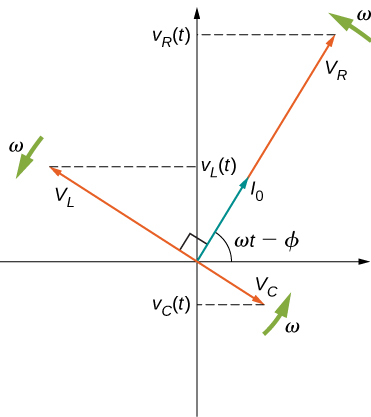
15 4 Rlc Series Circuits With Ac Physics Libretexts
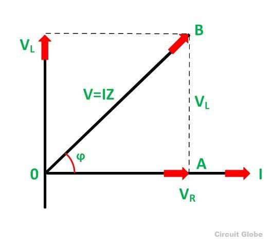
What Is Rl Series Circuit Phasor Diagram Power Curve Circuit Globe
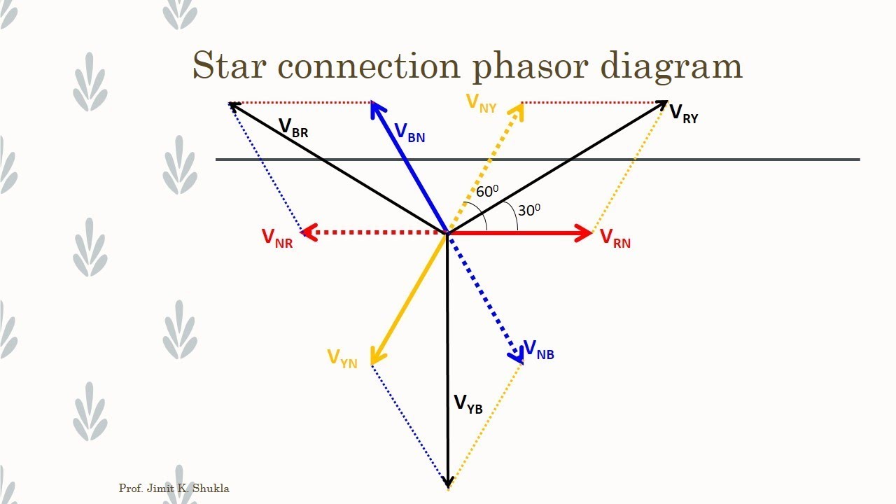
Diagram Electrical Phasor Diagram Full Version Hd Quality Phasor Diagram Chartdiagram Lineakebap It

Phasor diagram of single phase induction type energy meter 6.
Single phase energy meter phasor diagram.

Phasor Diagram For The Interfering Fields Top And The Resulting Power Download Scientific Diagram
Gps Signal Phasor Diagram Describing Carrier Tracking Loop Operation Download Scientific Diagram
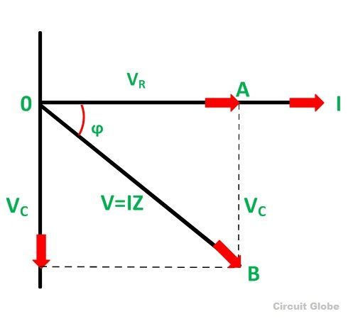
What Is Rc Series Circuit Phasor Diagram And Power Curve Circuit Globe

Phasor Diagrams For Amplitude Left Panel And Phase Right Panel Download Scientific Diagram
Source : pinterest.com
